
W tym artykule dowiesz się o aktualnie wydanej wersji oprogramowania dotyczącej produktu :
- Leica Cyclone 3DR 2020
Contents:
- What's New
- Manual adjustment of color gradient
- Cut/Copy/Paste between documents
- Extraction of cones
- CloudWorx - Importing RGB pictures
- Anti-Clash Script
- Reverse Engineering - Reversing and Outside/Inside Displaying for CAD objects
- Reverse Engineering - Surfaces sewing
- Reverse Engineering - Interface with Hexagon Arms
- Exporting to a DXF file
- Sending objects to Hexagon Mine Plan 3D
- Limit Box Editing
- Polyline - Name Displaying
- Improvements
- Leica Cyclone 3DR 2020.0.0 Compatibility
- Recommended Computer Specifications
- Licensing
What’s New
This is a major release, which incorporates some user-favorite functionalities of 3DReshaper into Cyclone 3DR including: manual adjustment of color gradient, creation and editing of cones, cut/copy/paste between documents and more.
In addition to improving the parity of 3DReshaper and Cyclone 3DR, new features are also released in the 2020 version including RGB pictures importing from CloudWorx, CAD interoperability improvements, several new Reverse Engineering functionalities and a “Anti Clash” command added in the favorite scripts.
According to the maintenance expiration date policy, users under maintenance on April 1st may access version 2020.0.0 with no new license required.
Manual adjustment of color gradient
This user-friendly tool is inspired by the popular tool in 3DReshaper.
After opening the Edit Color dialog box, the user can manually adjust the gradient, select preset gradients (default ones or saved gradients by the user) or create a new gradient preset.
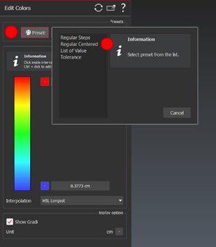
Figure 1. Selecting preset color gradient.
To apply a preset color gradient:
- Hit Preset
- Select the kind of gradient. Note that for all the default presets, some parameters are available in the dialog
- Regular Steps – Parameters: Number of steps
- Regular Centered – Parameters: Origin and Step
- List of Values – Parameters: List of values
- Tolerance – Parameters: Max tolerance and min tolerance

- Figure 2. Selecting preset color gradient.
To adjust the gradient manually, click on the colored gradient in the Edit Colors dialog box to edit the custom gradient:
- Double-click (or Ctrl+Click) in order to add a new range in the gradient
- Click on a range to modify its border values;
Click on a range to adjust the color properties: definition of the colors of the Min and Max values, with the possibility to assign one single color for the whole range (“synchronize color” option checked) or a gradient of colors between 2 colors (“synchronize color” option unchecked) (3 – right);
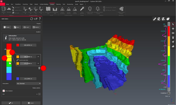
Figure 2. Showing the manual gradient edition options: adding/deleting a range, changing a border, modifying min/max values, choosing/configuring the color.
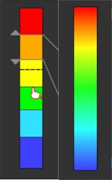
Figure 3. the gradient on the left displays the Synchronize Color option on. The gradient on the right has the Synchronize Color option off.
- Drag and drop the common border of two ranges to adjust the scale
- Click on the “bin” icon to delete the selected range
This feature is available to users with the Standard license.
Cut/Copy/Paste between documents
This new feature is very helpful when two or more Cyclone 3DR documents are launched and when one wants to duplicate an object from one document into another instance. Effort was made to replicate the actions used in Windows applications for simplicity.
Before proceeding, please ensure that:
- Both Cyclone 3DR documents are opened.
- Objects must be selected before the cut or copy execution.
- Following objects can be transferred between two projects: point clouds, meshes, contours, polylines, geometric shapes, CAD objects and images.
- Usual shortcuts for cut/copy/paste “CTRL+X/C/V” work in Cyclone 3DR.
Different methods are available to execute the cut/copy/paste commands, after selecting the objects.
- HOME MENU: Go to the Home menu and select the appropriate command.
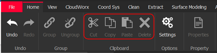
Figure 3. Home Menu features
- 3D SCENE: Use the right click of the mouse on the selected object(s) to cut/copy. A right click directly on the scene to paste is also available.

Figure 4. Right click through the 3D scene
- TREE VIEW: A right click on the selected object(s) provides cut and copy commands. A right click on the expected folder provides the paste option.
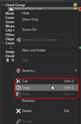
Figure 5. Right click through the tree
- SHORTCUTS:
- CTRL+X : Cut
- CTRL+C : Copy
- CTRL+V : Paste
This feature is available to users with the Standard license.
Extraction of cones
This new feature is migrated from 3DReshaper and provides for the creation and editing of cones. The best geometric shape of a cone can also be calculated from the following objects: clouds, meshes, polylines and CAD objects. This feature can be useful for many fields: CAD and Manufacturing Industry, Heritage and Architecture as well as clear applications in Infrastructure and Construction. In our example below, a cone is extracted and calculated to get the curvature of a water tower.
To use this command, select Cone from the Extract Menu.
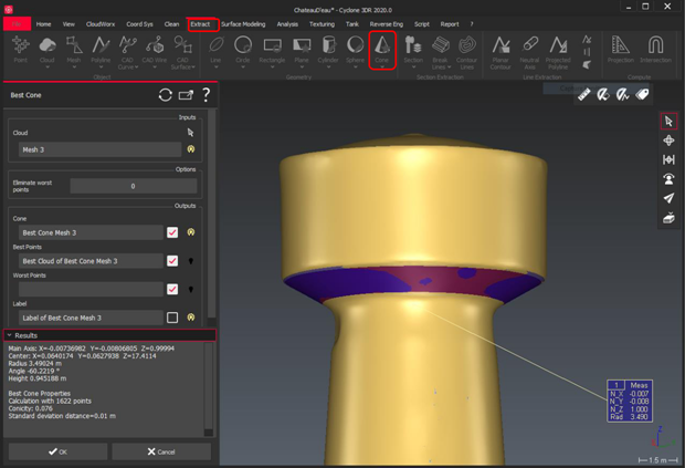
Figure 6. A best cone is created from a cloud. Edit/Draw/Best Cone are displayed in the Extract Menu.
This feature is available to users with the Standard license.
CloudWorx – Importing RGB pictures
The CloudWorx plugin has been updated so that the Convert to Cloud command now provides the possibility to import RGB images from LGS files. While connected to a JetStream project or opening an LGS file with the CloudWorx plugin in Cyclone 3DR, the user can check the Images option to import the wanted pictures in the Convert to Cloud dialog box.
The workflow to run this tool is:
- Go to CloudWorx
- Open the streamed cloud of the project through different ways (JetStream, LGS).
- Define the area of interest of the project by creating a Limit Box (this step is not necessary but is recommended to reduce the volume of the point cloud).
- Launch the Convert to Cloud command .
- Check the Images option to import the expected RGB pictures.
- Images will be represented by mirrored spheres in the 3D view.
- Double click on a sphere to enter the pano view.
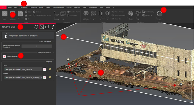
Figure 7. CloudWorx Dialog box for the “Convert to Cloud” command. Importing images can be un/checked.
This feature is available to users with the Standard license.
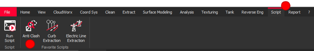
Anti-Clash Script
The 2020.0.0 version provides an Anti-Clash feature in the Script Menu which allows users to quantify the overlap of different kind of objects. This new script allows the user to get the percentage of non-matching areas between two objects which are supposed to match. This script is also available in GitHub.
The workflow to run this tool is:
- Select the object to inspect (at least one cloud).
- Select the reference (at least one mesh or CAD model).
- Go the Script menu.
- Launch the Anti-Clash button.
- Both scripting windows and the settings dialog box Results are displayed.
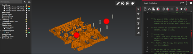
Figure 8. Example showing a project BEFORE launching the Anti-Clash inspection of columns (CAD object) with the point cloud of a level. Scripting dialog box are displayed. Obviously 5 columns are missing in the point cloud.
- Select the settings
- AntiClash Threshold: The percentage of non-overlapping area to consider anti-clash
- Maximum Searching Distance (in meters): The maximum distance to compare the cloud versus the model

- The Anti-Clash command will provide the percentage of anti-clash result of the inspected objects and will create a mesh, resulting from the non-matching area.

Figure 8. Same example AFTER launching the Anti-Clash inspection of columns. The script returns the 5 meshes (in red and blue) which represent the 5 missing columns.
This feature is available to users with the Standard license.
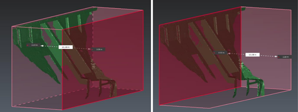
Reverse Engineering – Reversing and Outside/Inside Displaying for CAD objects
Options for rendering CAD objects have been improved in the 2020.0.0 release. Similar to the tools previously available for meshes, users can now use the Reverse function to invert the coloration of CAD objects.
Right click on the object and select Reverse. Or use the keyboard shortcut “i” after selecting the object.
The front faces default color is light grey, and the back faces default color is dark grey.
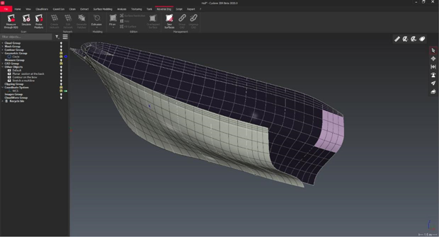
Figure 9. View with front and back faces of a CAD object.
This feature is available to users with the Standard Edition.
Reverse Engineering – Surfaces sewing
A new command in the Reverse Engineering menu allows to sew CAD surfaces in order to merge two or more object into a single object which can speed up calculations against the CAD objects as well as open possibilities for additional CAD applications that require single objects.
- Select several CAD surfaces
- Define a tolerance
- Select OK, Exit to accept the parameters and sew the surfaces
- The surfaces will be sewn together into a unique CAD surface/object.
This supports the management the topology of CAD surfaces and create CAD solids from CAD surfaces.
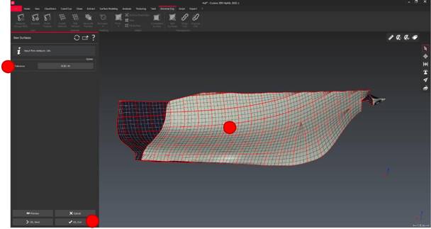
Figure 10. Sewing processing: this view shows CAD objects BEFORE sewing with common red contours.
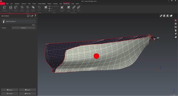
Figure 11. Sewing processing: this view the sewed CAD object. The internal red contours are consequently removed AFTER the process.
This feature is available to users with the AEC Edition.
Reverse Engineering – Interface with Hexagon Arms
Connection to an RDS Arm is now available in Cyclone 3DR. This new feature massively reduces the time from capture to import since he can get the data from the sensor to Cyclone 3DR in real time. This gain of time can also be increased if the user decides to immediately get a mesh from the scanner.
The new interface with the measuring arm is helpful for the Manufacturing Industry.
For this application, three main commands are available in the Reverse Engineering Menu.
- Measure through RDS: This command allows you to scan or probe cloud(s) and/or point(s) using an arm. Connect the arm and launch the command.
- Simulate: This command allows you to simulate a scan by uploading a .nsd of a previous scan. No selection required to launch the command. To create the .nsd file required for the simulation, do a scan with the command Scan \ Measure through RDS and then export the cloud as a .nsd file through the command File > Export > Export Selected Cloud(s).
- Probe Feature: This command allows you to measure geometry(ies) using a probe. Connect the arm and launch the command. This command is disabled if the arm is not in probe mode.
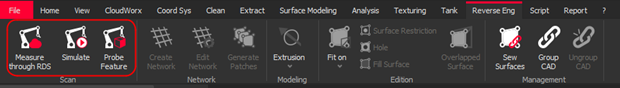
Figure 12. Screenshot of Reverse Engineering Menu. Hexagon Arm interface is located on the left.
This option will only appear when connection to a “RDS arm” is detected.
RDS Arm workflows are detailed in the Cyclone 3DR online help.
This feature is available to users with the AEC Edition.
Exporting to a DXF file
Users now have the option to adjust text spacing while exporting polylines to DXF. Some information can be displayed and repeated along the polylines. The spacing is the step between repeated texts, which can now be configured by the user.
To run this tool:
- Select the objects you want to export or proceed to step two if you want to export more than individual object(s)
- Go to the File Menu and click on the Export button
- Select the option among possibilities: All project / Visible objects / Selected Objects
- Define the folder, the name and the type of the exported file.
- If you do an export to a .dxf file, a new setting will appear on the screen. It is now possible to un/check the Distance between texts option and to define the value of this distance.
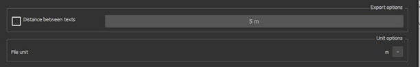
Figure 13. View of the option in the File>Export Menu while exporting to a .dxf file
- Validate the export.
This feature is available to users with the Standard license.
Sending objects to Hexagon Mine Plan 3D
The Surveying Edition of the 2020.0.0 release includes the option to send objects to Hexagon Mine Plan 3D. this provides a simple and direct connection for users of Mine Plan 3D to bypass the export/import process and simplify and reduce the time of their data transfer.
Note that this procedure is now the same for sending objects to Hexagon Mine Plan 3D and AutoCAD.
The following information is important to use the new feature:
- This feature can only be used when both Cyclone 3DR and MP3D are launched.
- It works with the following objects: polylines, point clouds and meshes.
- The user can choose whether to Export in UCS
The exporting to MP3D can be done different ways:
- SCENE: After selecting the objects that need to be exported, right click on the object
- Select SendTo
- Then select Mine Plan 3D

Figure 14. View of the 3D Scene while using the right click workflow.
- FILE MENU: After selecting the objects that need to be exported, the user can go the File menu
- Click on Send to
- Then select Mine Plan 3D
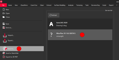
Figure 15. View from the Menu File > Send To > Mine Plan
- ANALYSIS > 2D PREVIEW / EXPORT: While using the 2D Preview workflow from the Analysis menu, the Send to other application now supports sending data to Hexagon Mine Plan 3D.

Figure 16. View from the 2D Preview dialog box
- TEXTURING > EXTRACT ORTHOIMAGE: While using the Extract OrthoImage command in the Texturing Menu, Send to other application now supports sending data to Hexagon the Mine Plan 3D.
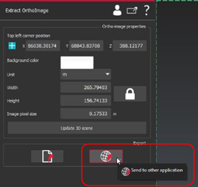
Figure 17. View from the Extract OrthoImage dialog box
This feature is available to users with the Surveying Edition.
Limit Box Editing
With the release of Cyclone 3DR 2020.0.0, all faces of a Limit Box can now be edited without having to rotate the 3D scene to move the back faces to the front of the view. This feature makes editing limit boxes easier, faster, and more user friendly.
While editing a limit box, hold the left SHIFT key to access to the hidden faces of the box and drag the face to move the limits of the box.
No key pressed SHIFT key pressed
Figure 18. In this case, the user can drag and drop the “front” faces of the box (front, up and left). In the 2020.0.0 version of Cyclone 3DR, the user can now hold the left SHIFT button of the keyboard and has the option to drag and drop the hidden faces (bottom, back and right in the case showed above).
This feature is available to users with the Standard license.
Polyline – Name Displaying
Users can now choose to display the name of a polyline object within the 3D scene.
To activate this new option:
- Click on the Representation settings in the tree of the project
- The Show Text option is available and can be defined by the user for each object.
- When selected, the name of each polyline will be present within the 3D view.
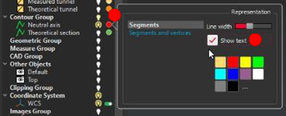
Figure 19. View of the Representation Dialog box

Figure 20. Example of text displaying from polylines
This feature is available to users with the Standard license.
Improvements
- 3D Scene: The color gradient is no longer hidden when the object is selected.
- 3D Scene: Inspected profile quotations displayed in perspective are now produced more quickly.
- Analysis > Compare inspect > Cloud vs Mesh: Significant reduction of computation time.
- Surface Modeling > Smart Modeling Command: major reduction of computation time for DTM, DSM and Building Extractor.
- Analysis > Measure > Volume from Elevation
- During the Volume from Elevation analysis, if too many planes are generated, they will be automatically hidden for a more user-friendly view of the scene. In this case, a message is opened in a dialog box to warn the user that computing can take time.
- After the Volume from Elevation analysis, a detailed chart is now available and automatically added into the reporting data.
- Analysis > Volume Over Under:
- During the Volume Over Under analysis, the value of the step between subsections can be manually entered by the user, which improves the volume computation stability and accuracy.
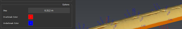
Figure 21. View of the manual step value option
- After the analysis, a detailed chart is now available and automatically added into the reporting data.
- Analysis > Section VS: Better positioning of quotations on sections aligned along the Z axis.
- CAD Object –Triangulated surfaces are now embedded inside the CAD object after import.
- CAD Object – CAD objects can be extracted from mesh
- Export ASCII: the user can now select the number of decimal places to display.
- File > Import: While importing a file by a drag and drop, a dialog box containing importing options is now displayed. For files which do not require advanced options, it is now possible to drag and drop a file without displaying this dialog box. This can be defined in the general settings.
- Script > Run Script: API documentation is now directly accessible from the dialog toolbar.
- Script: Add new methods in SImage class to edit image parameters. Old methods from SPoly class are now deprecated.
- Surface Modeling > 3D Mesh: Better management of areas with low density by using scanning directions information.
- Surface Modeling > 3D Mesh: Fix non manifold area in the output mesh.
- Surface Modeling > 3D Mesh: Optimize topology.
Leica Cyclone 3DR 2020.0.0 Compatibility
- Cyclone 3DR is compatible with CLM 1.8 and higher.
- Cyclone 3DR is compatible with JetStream Enterprise 1.3 and higher.
- Cyclone 3DR is compatible with LGS files.
- Cyclone 3DR is compatible with Cyclone IMP databases from Cyclone 6.0 or higher, however improved rendering will only be seen with IMPs from Cyclone 9.3 or higher.
Recommended Computer Specifications
- CPU: 2 GHz Dual Quad Core i7 or higher (i5 minimum)
- RAM: minimum 16 GB or more for 64-bit OS
- Graphic Card: NVidia Quadro or GeForce 1 GB (with OpenGL support, versions 4.3 or higher)
- Operating system: Microsoft Windows 7, 8, 10 (64 bits supported)
- Hard Disk: 3 GB free disk space
Licensing
All users with valid CCP or CCP which was valid as of 1 April 2020 for Cyclone 3DR, can run this new version of Cyclone 3DR.
All users with valid CCP or CCP which was valid as of 1 April 2020 for 3DReshaper, can run this new version of Cyclone 3DR with no new license required.
Users with 3DReshaper licenses with expired CCP must migrate to Cyclone 3DR in order to continue to access updates and support. Please contact your sales or support personnel for more information.
Komentarze
Komentarze: 0
Zaloguj się, aby dodać komentarz.